
Cabling overview
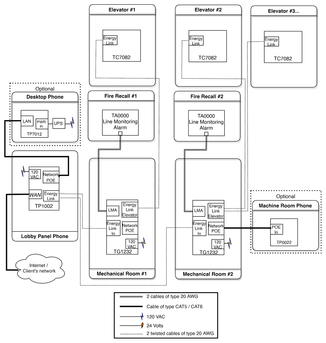
Wiring - Machine room (TG1232 or TG1264)
Detailed enclosure connection for TG1232: TG1232 Cabling Schematics.pdf
Detailed enclosure connection for TG1264:TG1264 Cabling Schematics.pdf
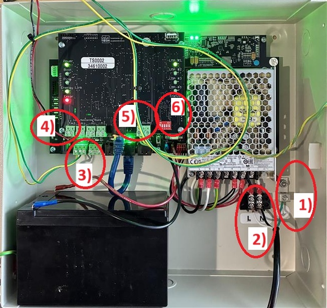
Install the equipment with a 15A circuit breaker. It is recommended to use an emergency power supply if available.
-
Connect the ground wire to the screw located at the bottom of the enclosure
-
Connect the 120 VAC Line (L) and Neutral (N) to the terminals at the bottom of the enclosure
-
Connect the Thunder Phone’s ELL, ELH, and shield lines to the Cabin # terminal using a twisted-pair telephone cable.
-
Connect LMA− and LMA+ (terminal #1) to the communication failure alarm panel of the firefighter recall system.
-
Connect the lobby phone twisted pair to ELL and ELH
-
Set the gateway’s physical address using the dipswitches. Each gateway in the machine room must have a unique address, starting at 1
-
Ensure the enclosure switch is in the OFF position
-
Connect the battery
-
Restore the 120 VAC power supply
-
Turn the enclosure switch to ON
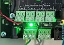
Startup Validation - Machine room TG1232
-
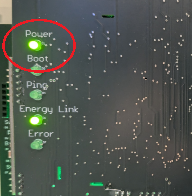
Validate that the LED “Power” is ON
-
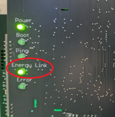
Validate that LED “EL” is ON
-
Validate that the Cabin LED where you connected your elevator (ELL-ELH) is ON (Troubleshoot)
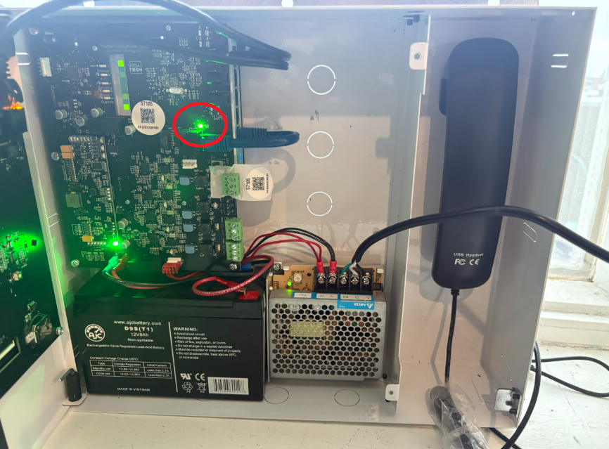
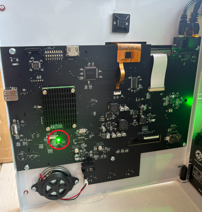
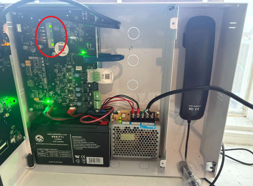
Startup Validation - Machine room TP1002
-
Validate that the LED “Power” is ON next to the RJ45 connector. (Troubleshoot)
-
Validate that the LED “Power” is ON on the back of touchscreen. Note that the LCD takes around 30 seconds to display (Troubleshoot)
-
Validate that LED 1, LED 2 and LED 5 are are ON on the Router (Troubleshoot)
-
Validate that the LEDs next to the machine room connector (ELL/ELH) are ON (Troubleshoot)
Installation and wiring is complete.
Next step : Device Discovery