
Security information
-
Equipment for restricted-access areas only.
-
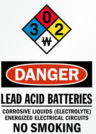
The supplied resistors and fuse limit discharge current to 15 A.
-
Disconnect 120 VAC power during any intervention inside the enclosure.
-
Replacing the BATTERY with an incorrect type may compromise SAFETY (see Maintenance section for replacement instructions).
-
Disposing of a BATTERY in fire, a hot oven, or by mechanically crushing or cutting it may result in an EXPLOSION.
-
Exposing a BATTERY to extremely high temperatures may result in an EXPLOSION or leakage of flammable liquid or gas.
-
Subjecting a BATTERY to extremely low atmospheric pressure may result in an EXPLOSION or leakage of flammable liquid or gas.
|
|
|---|
Installation and Wiring for Low-Rise Systems
Next step: Installation (Low-rise)
Installation and Wiring for High-Rise Systems
Next step: Installation (High-rise)