
1. Configure Contacts
You can configure emergency contacts directly from the Thunder Supervisor Touchscreen. Two types of contacts can be configured for each phone:
Contact Types
Dial
Used for external phone numbers such as cell phones, call centers, offices, or any other external destination.
Local
Used to contact local Vidatech Thunder phones. For example, a Thunder Cabin phone can contact a Thunder Desktop phone such as a TP7012.
Configure a "Dial" Contact
-
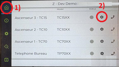
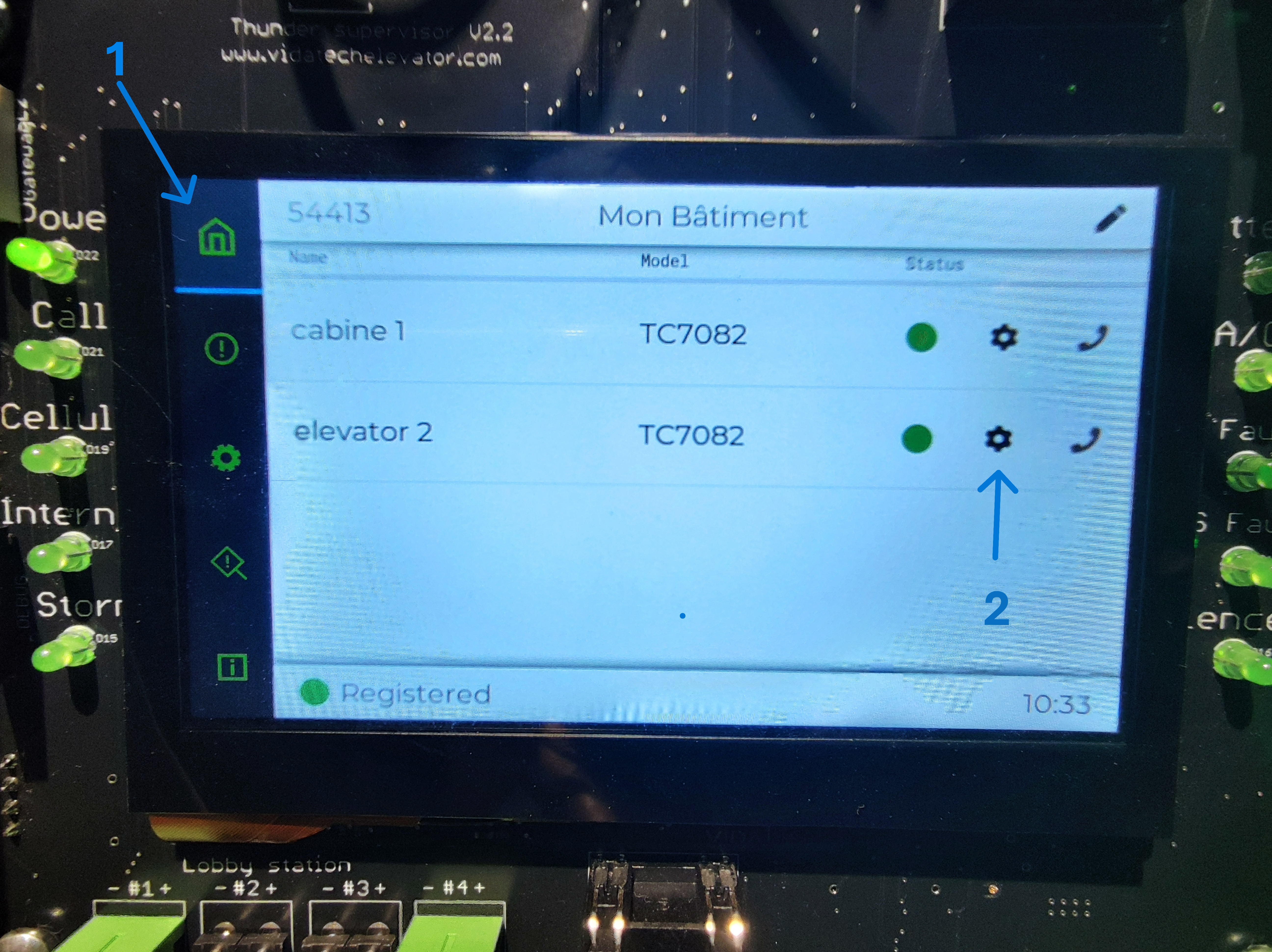
Go to the Home Menu.
-
Select Device Settings
-
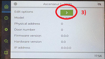
Select Edit Options
-
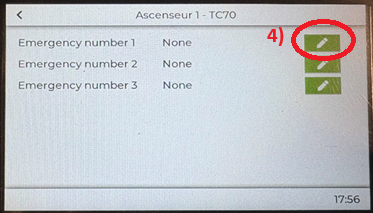
Select the first available number field.
-
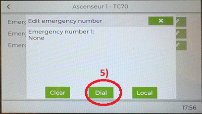
Select Dial.
-
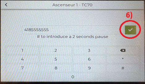
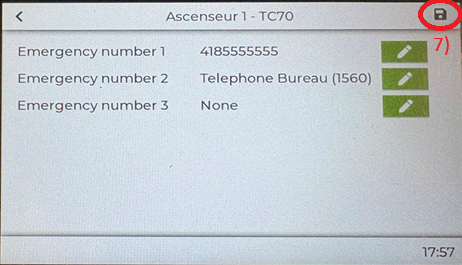
Enter the phone number, then press the Check icon.
-
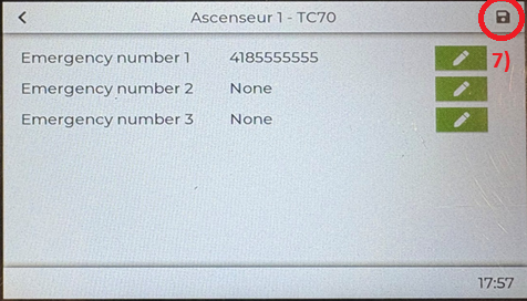
Verify the number and add additional numbers if required. Press Save.
-
Return to the Home Page and wait for device status to change from blue to green.
Configure a "Local" Contact
-
Go to the Home Menu.
-
Select Device Settings.
-
Select Edit Options.
-
Select the first available number field.
-
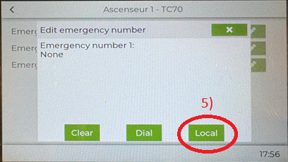
Select Local.
-
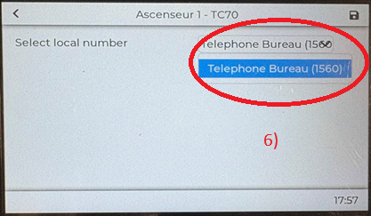
Select the Vidatech phone from the drop-down list.
-
Verify the selection and add additional numbers if required, then press Save.
-
Return to the Home Page and wait for the device status to change from blue to green.
2. Setup LMA (Line Monitoring Alarm)
Setup for a High-Rise System
On the supervisor screen, follow the steps below:
-
Access the Home Menu.
-
Select the Device Settings for the Thunder Phone you want to pair with a TA0000.
-
In the LMA Number parameter, select the appropriate LMA number. Ensure that the selected LMA number matches the corresponding LMA port on the gateway.
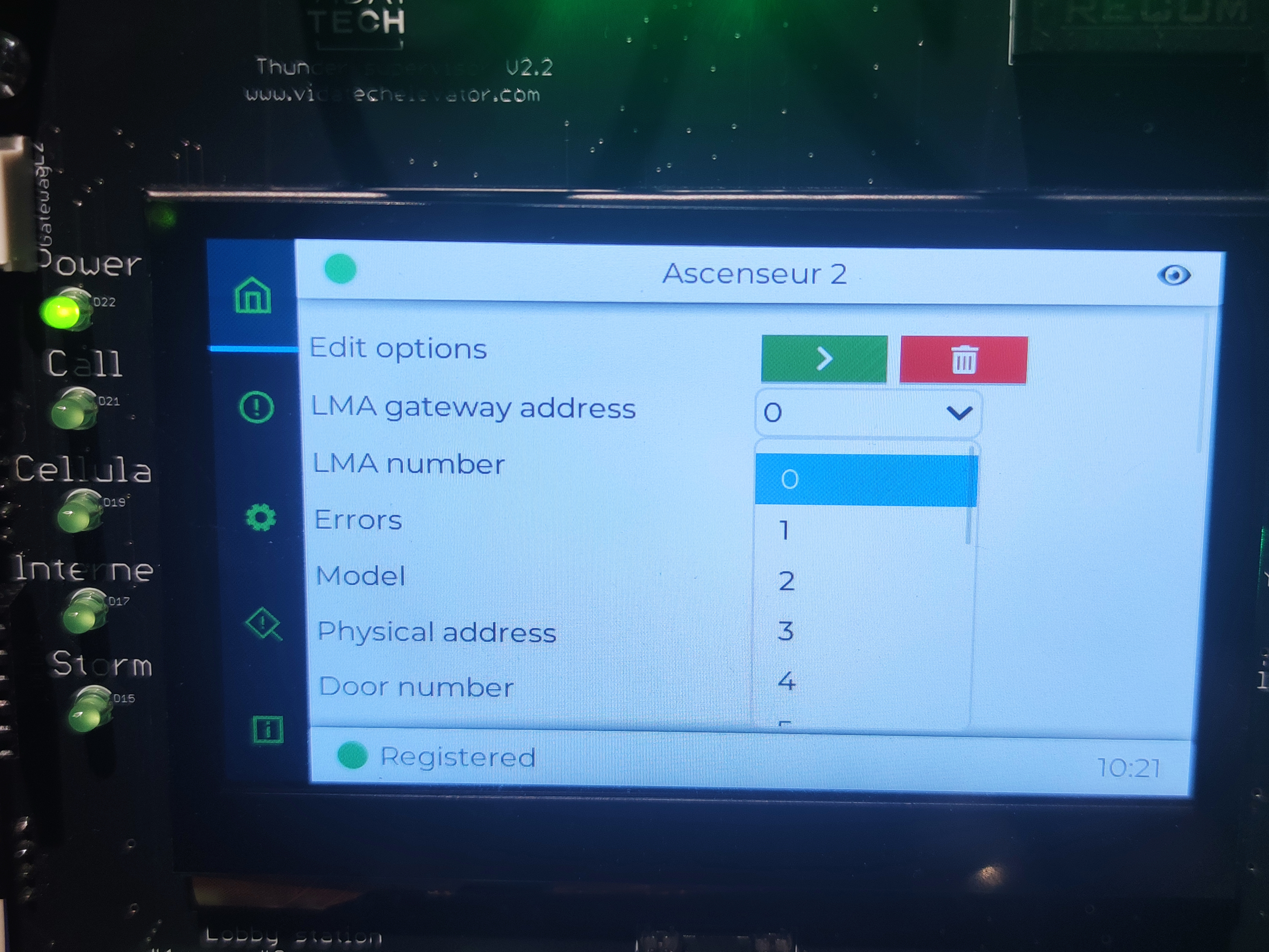
The LMA number parameter must match the LMA port on the gateway.
-
Configure the LMA Gateway Address.
This address corresponds to the TG1232 or TG1264 gateway located in the machine room. For High-Rise Systems, the configured gateway address must match the physical address set on the TG1232 or TG1264.
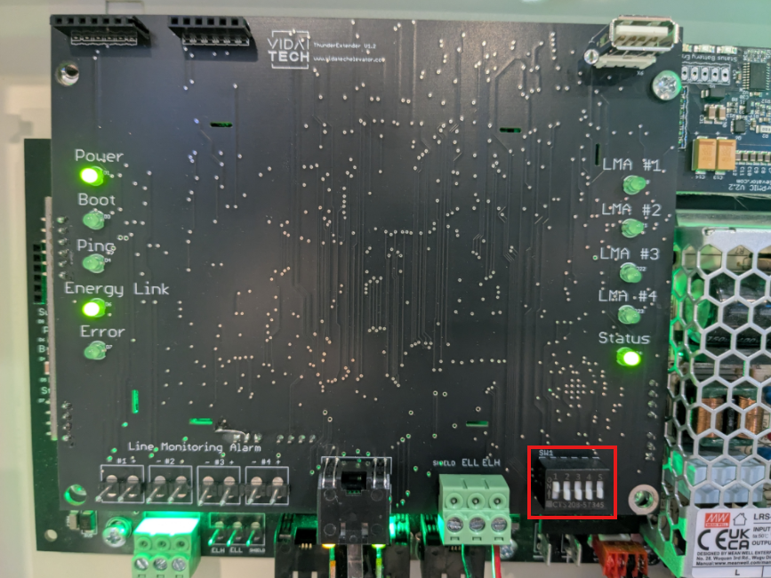
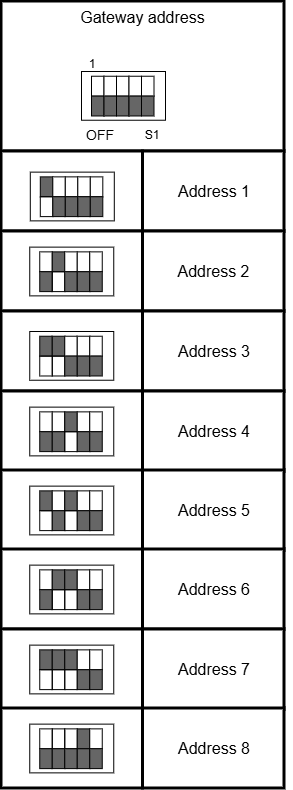
Each TG1232 or TG1264 must be assigned a unique physical address. Physical addresses must start at 1.
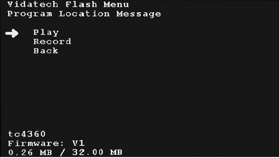
3. Record Location Message (Thunder Cabin Phone in COP)
The location message must be recorded directly on the Thunder Cabin Phone. It cannot be configured from the Thunder Supervisor.
|
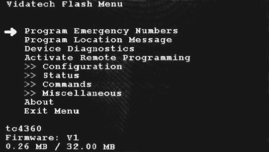
Main Menu Page To access the menu, press the ENTER button (on the rear display). Button Functions
|
|
Program Location Message
|
Configuration is complete.
Previous step: Internet and Update