
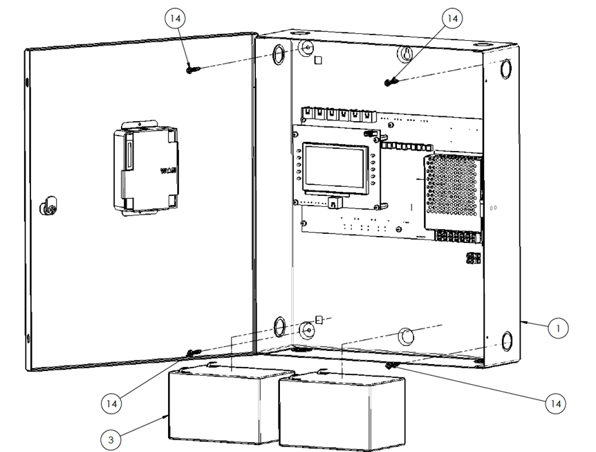
1. Mounting the enclosure
-
Remove the batteries from the enclosure
-
Mount the enclosure securely to the wall using four screws
-
Reinstall the batteries after installation
2. Cabling Overview
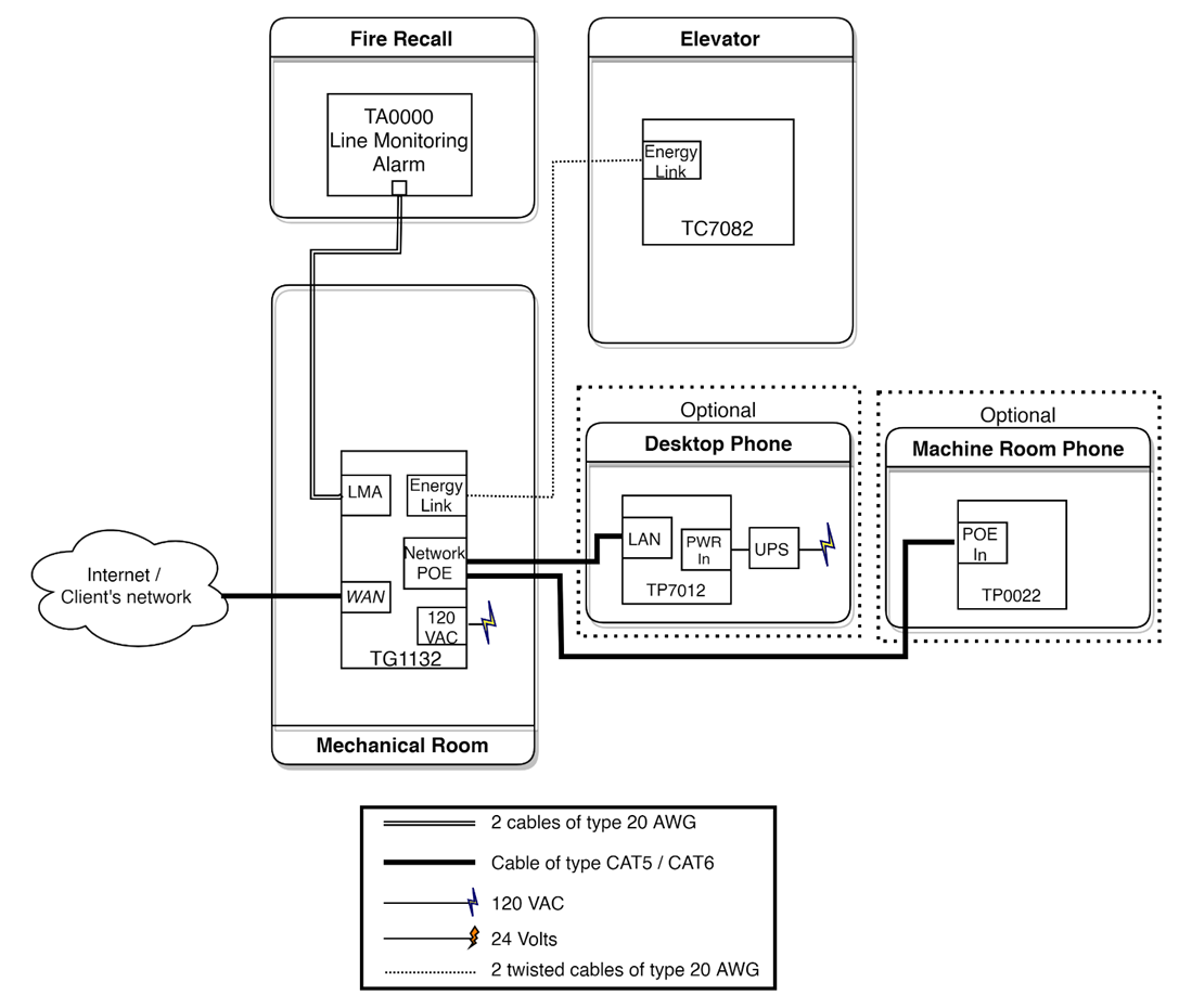
3. Wiring the enclosure
Detailed enclosure connection: TG1132 Cabling Schematics.pdf
Install the equipment with a 15A circuit breaker. It is recommended to use an emergency power supply if available.
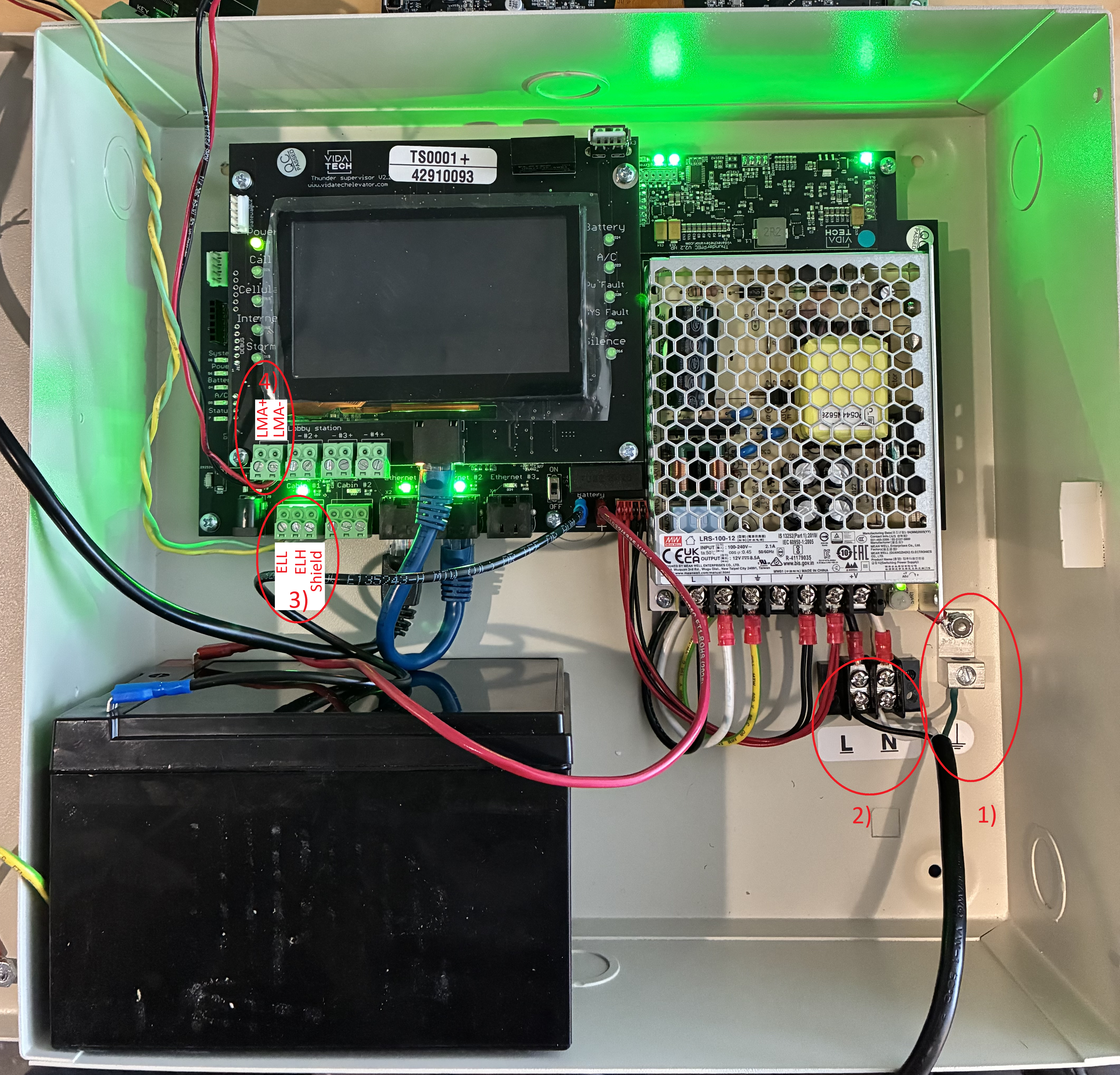
NOTICE! The 120 VAC power must be disconnected during any work inside the enclosure
-
Connect the ground wire to the screw located at the bottom of the enclosure
-
Connect the 120 VAC Line (L) and Neutral (N) to the terminals at the bottom of the enclosure
-
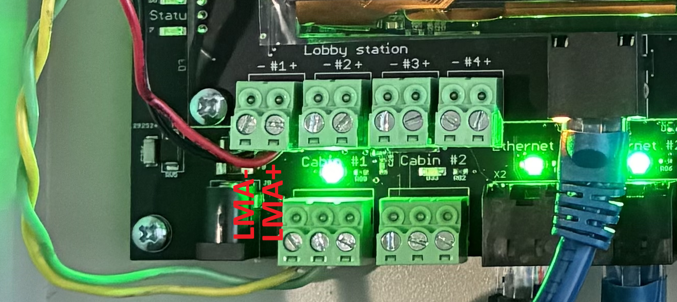
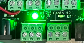
Connect ELL, ELH, and Shield using the twisted pair telephone cable to the Cabin # connector
-
Connect LMA- and LMA+ (Lobby Station #1 connector) to the communication failure alarm panel in the firefighter recall system
-
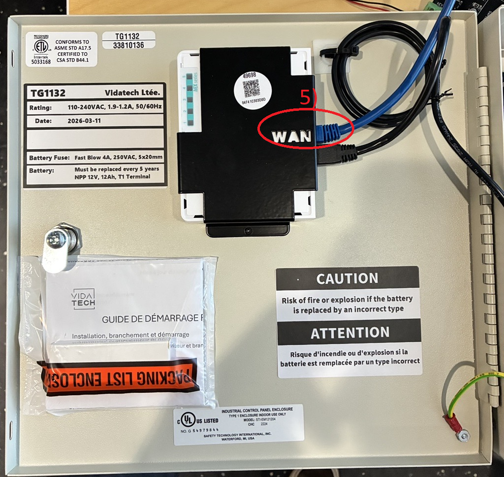
Connect the customer network to port 2 of the router (labeled WAN)
-
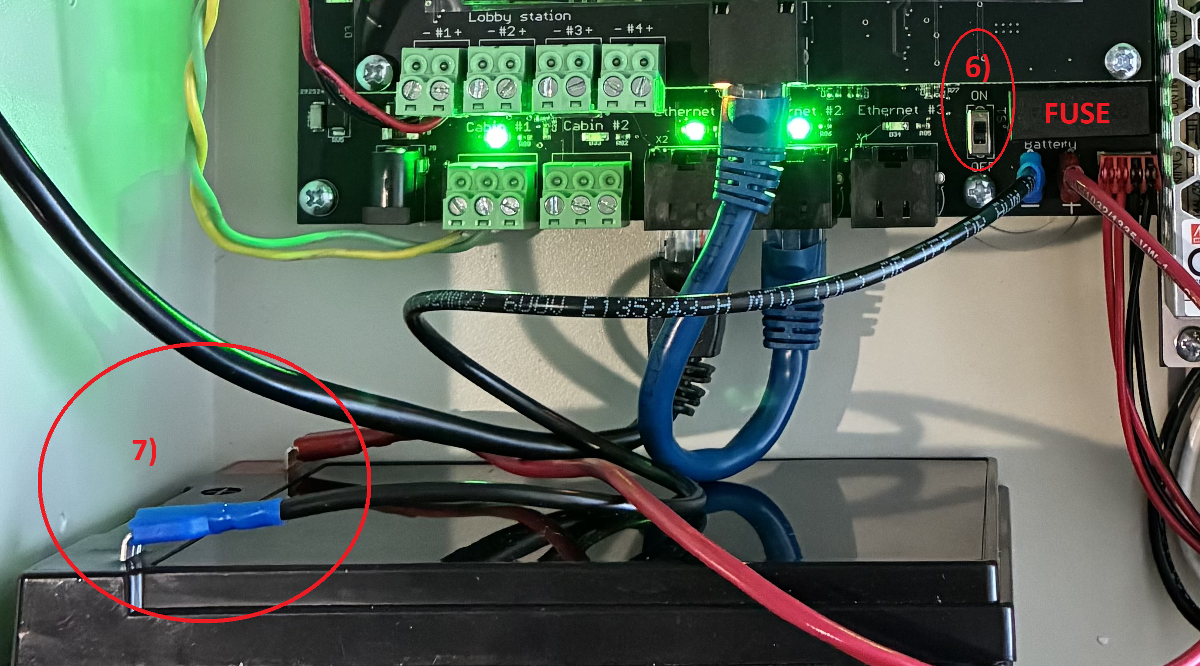
Ensure the enclosure switch is in the OFF position
-
Connect the battery
-
Restore the 120 VAC power supply
-
Turn the enclosure switch to ON
4. Startup validation
-
Validate that the LED “Power” is ON on your touchscreen. Note that the LCD takes around 30 seconds to display (Troubleshoot)
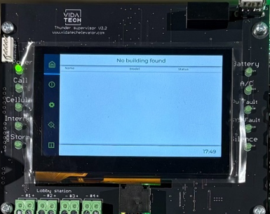
-
Validate that LED 1 and LED 2 are ON on the Router (Troubleshoot)
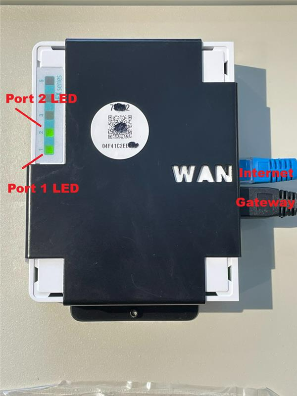
-
Validate that the Cabin LED where you connected your elevator (ELL-ELH) is ON (Troubleshoot)
Installation and wiring are complete.
Next step: Device Discovery