

Description
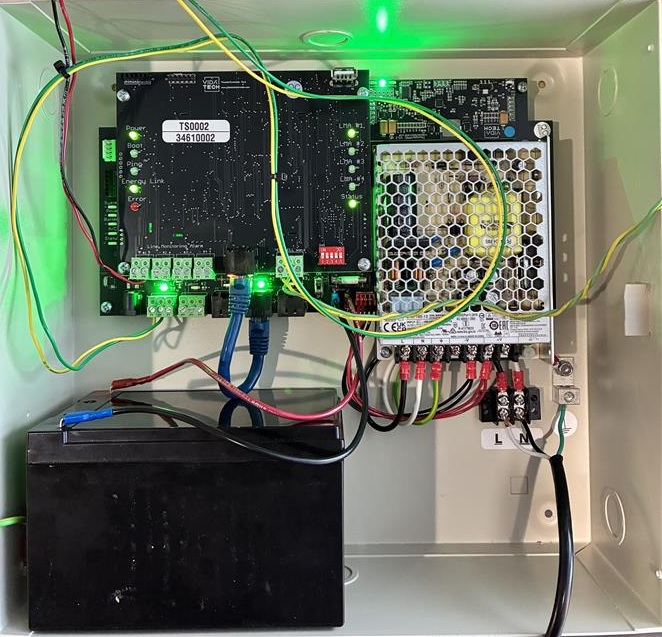
The TG1232 is a machine-room gateway used in Thunder High-Rise installations. It provides communication between Thunder cabin phones, Line Monitoring Alarms (LMAs), and the Thunder Supervisor.
The TG1232 includes a 4-hour battery backup capable of powering all connected devices during a power outage.
A single TG1232 can support:
-
Up to 2 Thunder Cabin Phones
-
Up to 4 Line Monitoring Alarms (LMAs)
Specifications
|
Specification |
Value |
|---|---|
|
Features |
Phone line monitoring, Battery Backup |
|
Mounting |
Wall Mount |
|
Enclosure |
Hinged Door with thumb lock, Powder Coat finish |
|
Dimensions (L × W × D) |
323 × 310 × 109 mm (12.7 × 12.2 × 4.3 in) |
|
Connection |
3 × PoE Ethernet, 2 × Energy Link |
|
Power |
1.4 A / 120 VAC |
|
Battery |
12V/14Ah ou 12Ah? |
|
Compliance |
ASME A17.1-2019, CSA B44-19 ASME A17.1-F2019 CSA B44-F19 |
|
Operating Temperature |
0–45 °C (32–113 °F) |
|
Weight |
8.45 kg (17.6 lbs) |
|
Warranty |
1-year warranty from the installation date |
|
Protocol / Communication |
SIP, VPN, DHCP, Energy Link, NTP, STUN |
|
Security |
TLS 1.3, Encrypted Firmware, AES256 |
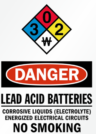
Security Notice
-
Equipment for restricted-access areas only.
-
The supplied resistors and fuse limit discharge current to 15 A.
-
Disconnect 120 VAC power during any intervention inside the enclosure.
-
Replacing the battery with an incorrect type may compromise safety.
-
Disposing of a battery in fire, a hot oven, or by mechanically crushing or cutting it may result in an explosion.
-
Exposing a battery to extremely high temperatures may result in an explosion or leakage of flammable liquid or gas.
-
Subjecting a battery to extremely low atmospheric pressure may result in an explosion or leakage of flammable liquid or gas.
Interface explanation
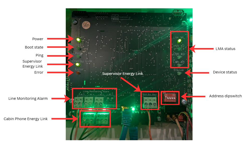
Power
LED status for power.
Boot State
Indicates when the device is booting. This LED turns ON during startup.
Ping
Indicates network communication activity.
Error
Indicates a system fault.
Line Monitoring Alarm Connector
Connects the LMA.
Cabin Phone Energy Link
Connects the Thunder Cabin Phone. The status LED turns green when a phone is detected.
Supervisor Energy Link
Indicates communication with the Thunder Supervisor. The LED is green when connected.
Address DIP Switch
Used to assign the gateway address. Each gateway must have a unique address.
Device Status
Displays the status of connected devices.
LMA Status
The corresponding LMA indicator turns green when an LMA is connected.
Enclosure Installation
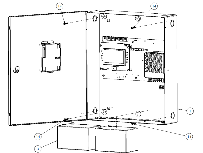
-
Remove the batteries from the enclosure before mounting.
-
Pre-drill mounting holes in the installation surface.
-
Install anchors appropriate for the wall type.
-
Reinstall the batteries after mounting.
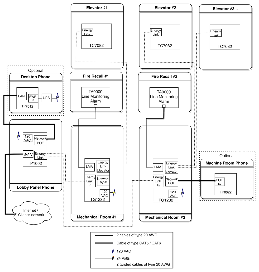
Wiring
High-Level Connection
Low level connection
Install the equipment on a dedicated 20 A branch circuit.
Use emergency power when available.
WARNING: Disconnect 120 VAC power before performing any work inside the enclosure.
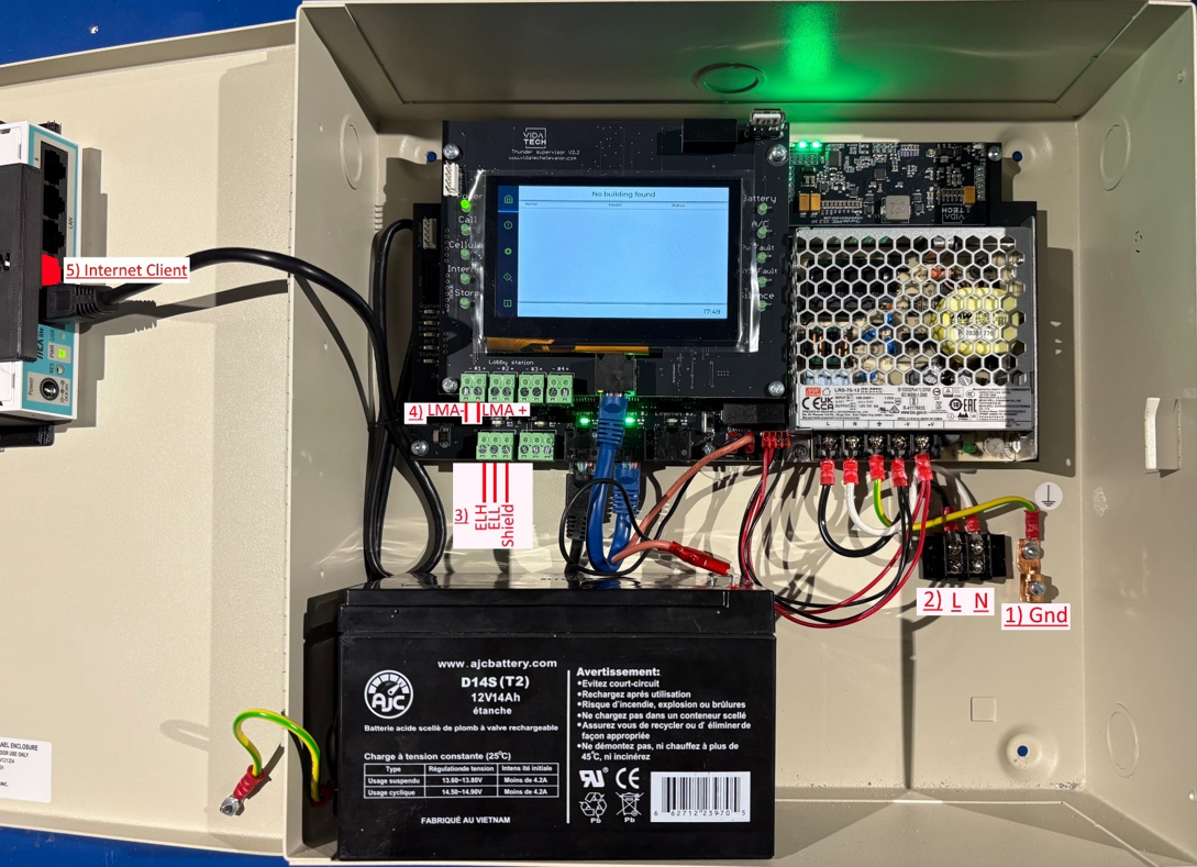
Wiring Procedure
-
Connect the ground wire to the grounding screw located at the bottom of the enclosure.
-
Connect the 120 VAC Line (L) and Neutral (N) conductors to the enclosure terminals.
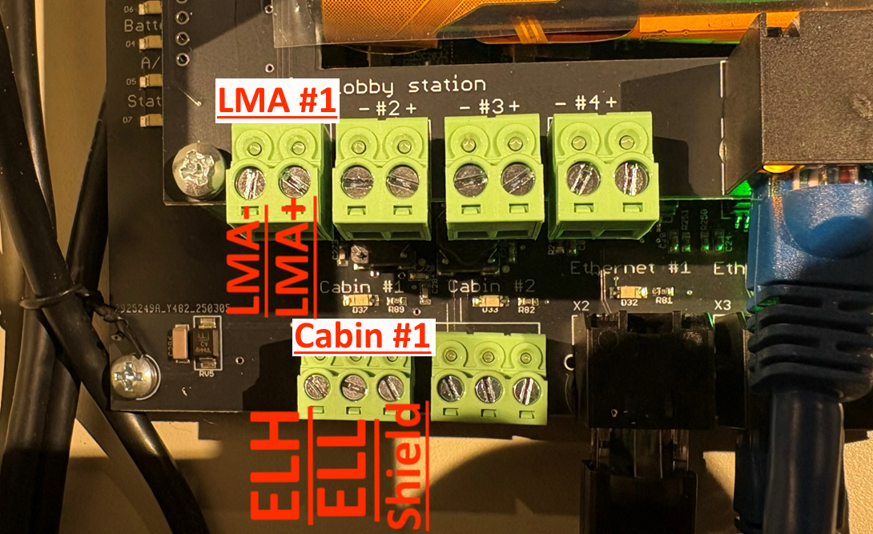
-
Connect ELH, ELL, and Shield using a twisted-pair telephone cable to the Cabin connector.
-
Connect LMA− and LMA+ to the communication loss alarm panel.
-
Connect the customer network to router port 2 (WAN).
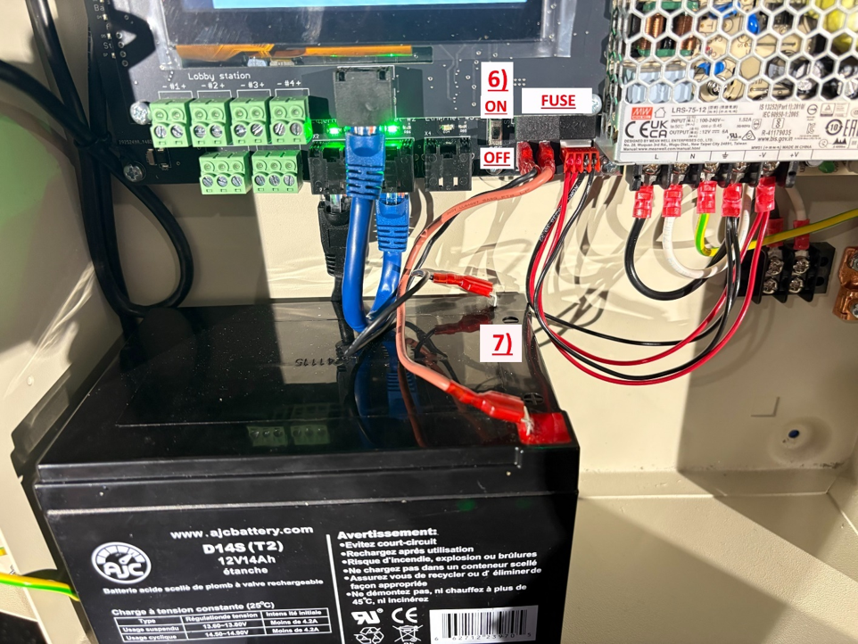
-
Verify that the enclosure power switch is in the OFF position.
-
Connect the battery.
-
Apply 120 VAC power.
-
Move the enclosure power switch to the ON position.
Startup
-
Complete the machine room enclosure wiring.
-
Perform a network speed test from the touchscreen diagnostics menu. Results should exceed 2 Mbps download and upload.
Navigation:
System Status → Diagnostic → Speed Test
-
Configure the emergency phone number from the machine room touchscreen.
Navigation:
Home Page → Device Settings → Edit Options → Emergency Number #1 → Dial → Save
-
On the cabin phone, perform a Device Diagnostic. All tests should display PASS.
Navigation:
Menu → Device Diagnostic
-
Record the location message.
Navigation:
Menu → Program Location Message → Record → Stop → Save
-
Perform a test call to the monitoring center.
-
Test the communication loss alarm panel from the LMA submenu.
Signification des leds
Error code
LEd signification
short description
talk about PMIC
Validation
The installation is considered complete when all of the following conditions are met:
-
The TG1232 powers on without active fault indications.
-
Network speed test results exceed 2 Mbps download and upload.
-
The emergency phone number has been configured and saved.
-
The cabin phone Device Diagnostic reports PASS for all tests.
-
The location message has been recorded.
-
A test call to the monitoring center is successful.
-
The communication loss alarm panel operates correctly.
-
All connected devices display a normal status.
Maintenance
Battery Replacement
-
Replace the batteries every 5 years to maintain the required 4-hour backup autonomy.
-
Contact Vidatech to order replacement batteries of the same model.
-
Before replacing the batteries, move the enclosure power switch to the OFF position.
-
If two batteries are replaced in the same enclosure, verify that the voltage difference between the batteries does not exceed 0.7 V before connecting them.
Fuse Replacement
Replace the battery fuse with a 4 A, 250 V, fast-acting 5 × 20 mm fuse.
Firmware Updates
During periodic inspections, check for and install available firmware updates using the machine room touchscreen.
Vidatech recommends performing this verification at least every 3 months.
Inspection
Perform the following inspection procedure to verify that the TG1232 and all connected devices are operating correctly.
-
Perform a test call to the monitoring center.
-
Ask the monitoring center operator to log in to Vidatech Storm using the 5-digit identifier displayed on the cabin phone.
-
Ask the monitoring center operator to verify that the video stream is functioning properly during the call.
-
Ask the monitoring center operator to send a message through the chat window.
-
In the cabin, press the Door Open button to respond "Yes" and the Door Close button to respond "No".
-
Verify that all connected devices in the machine room enclosure display a green status indicator.
-
Verify that the communication loss alarm panel is detected by the TG1232.