
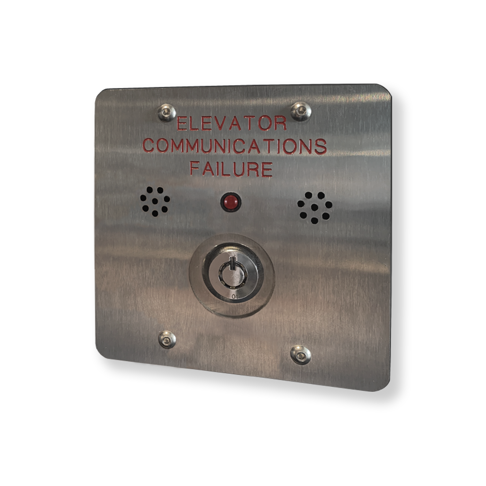
The TA0000 is a Phone Line Monitoring Alarm (LMA) equipped with an LED indicator and an audible buzzer. It activates both visual and audible alarms when it detects an error in the Thunder Emergency Communication System.
Specifications
|
Parameters |
Value |
|---|---|
|
Alarm input votlage |
12-24VDC (no polarity) |
|
LED output |
2.1VDC at 13mA |
|
Power consumption (idle) |
0.3W |
|
Power consumption (alarm) |
1.6W |
|
Alarm input wire gauge |
20 AWG |
|
Maximum Length |
600 m (2000 ft) |
Features
The TA0000 operates in two modes: Alarm Mode and Idle Mode.
Alarm Mode
In Alarm Mode, the red LED blinks and the buzzer sounds every 30 seconds to indicate an issue. The buzzer can be muted for 12 hours by turning the key. Muting the buzzer does not affect the LED, which will continue to blink until the issue is resolved.
Idle Mode
When no errors are reported, the TA0000 is in Idle Mode. In this state, the buzzer is silent and the alarm LED is off.
To test the buzzer and LED, turn the key switch to the ON position. The buzzer will sound and the LED will turn ON for as long as the key switch is held in the ON position.
Alarm sources
The following conditions will cause the TA0000 to enter Alarm Mode:
-
Device did not ping
-
Failed to register to local PBX
-
Failed to register to public PBX
-
Two or more devices with the same physical address
-
Issue with the camera
-
Issue with the audio
Installation and Wiring
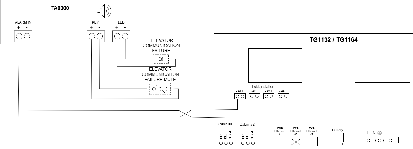
Installation with a Low-Rise system
In a Low-Rise System, the alarm input of the TA0000 must be connected to one of the four lobby station ports on the TG1132 or TG1164.
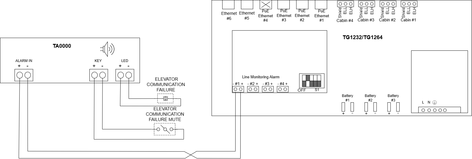
Installation with a High-Rise System
In a high-rise system, the alarm input of the TA0000 must be connected to one of the four Line Monitoring Alarm ports on the TG1232 or TG1264.
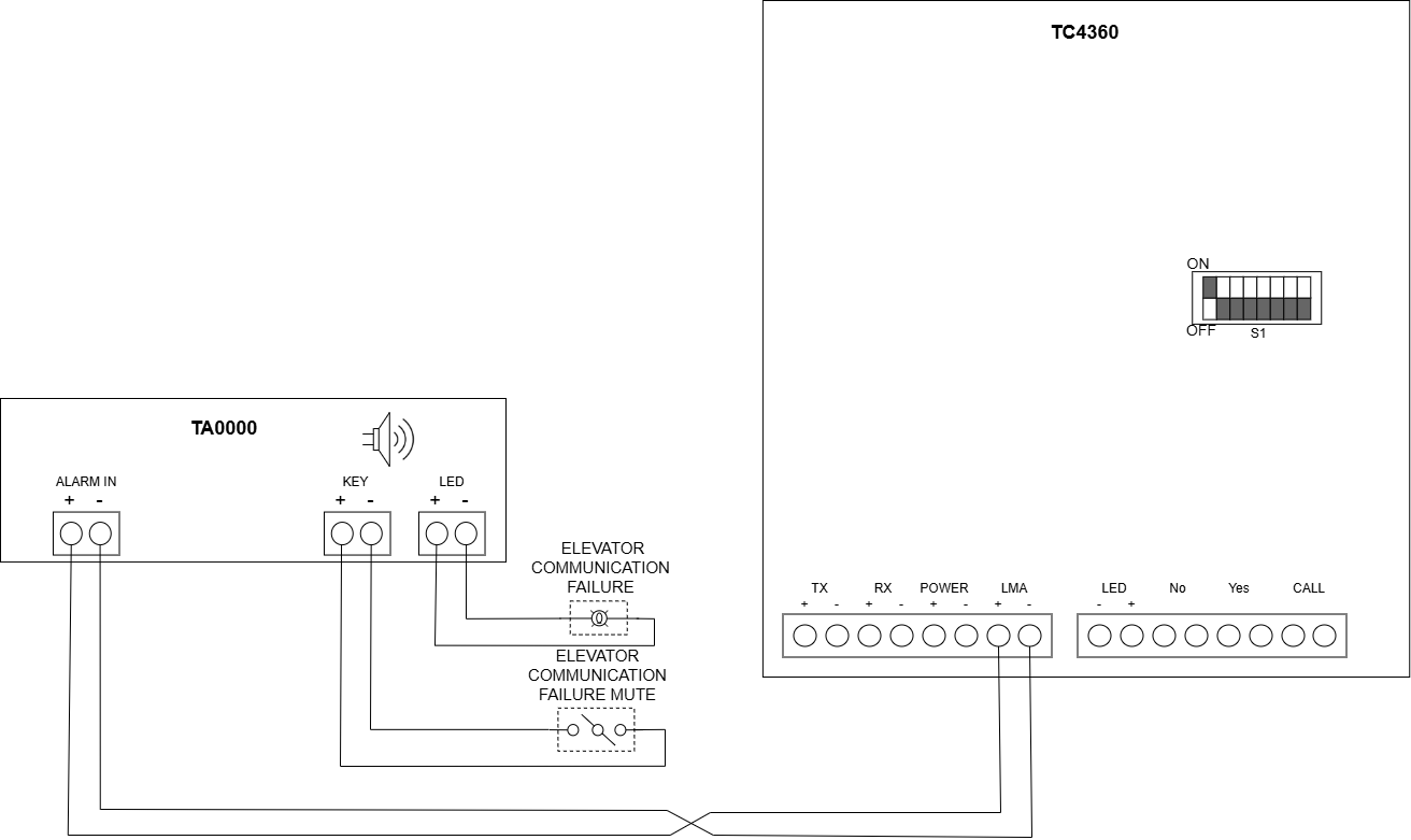
Installation with a LULA system
n a LULA system, the alarm input of the TA0000 must be connected directly to the LMA port on the TC4360.
Configuration
Configuration for Low-Rise and High-Rise Systems
Each Thunder Phone is associated with a single TA0000 and reports all errors to that TA0000. The TA0000 can be configured directly on the supervisor (TG1132, TG1164, or TP1002). Follow the steps below to configure the TA0000.
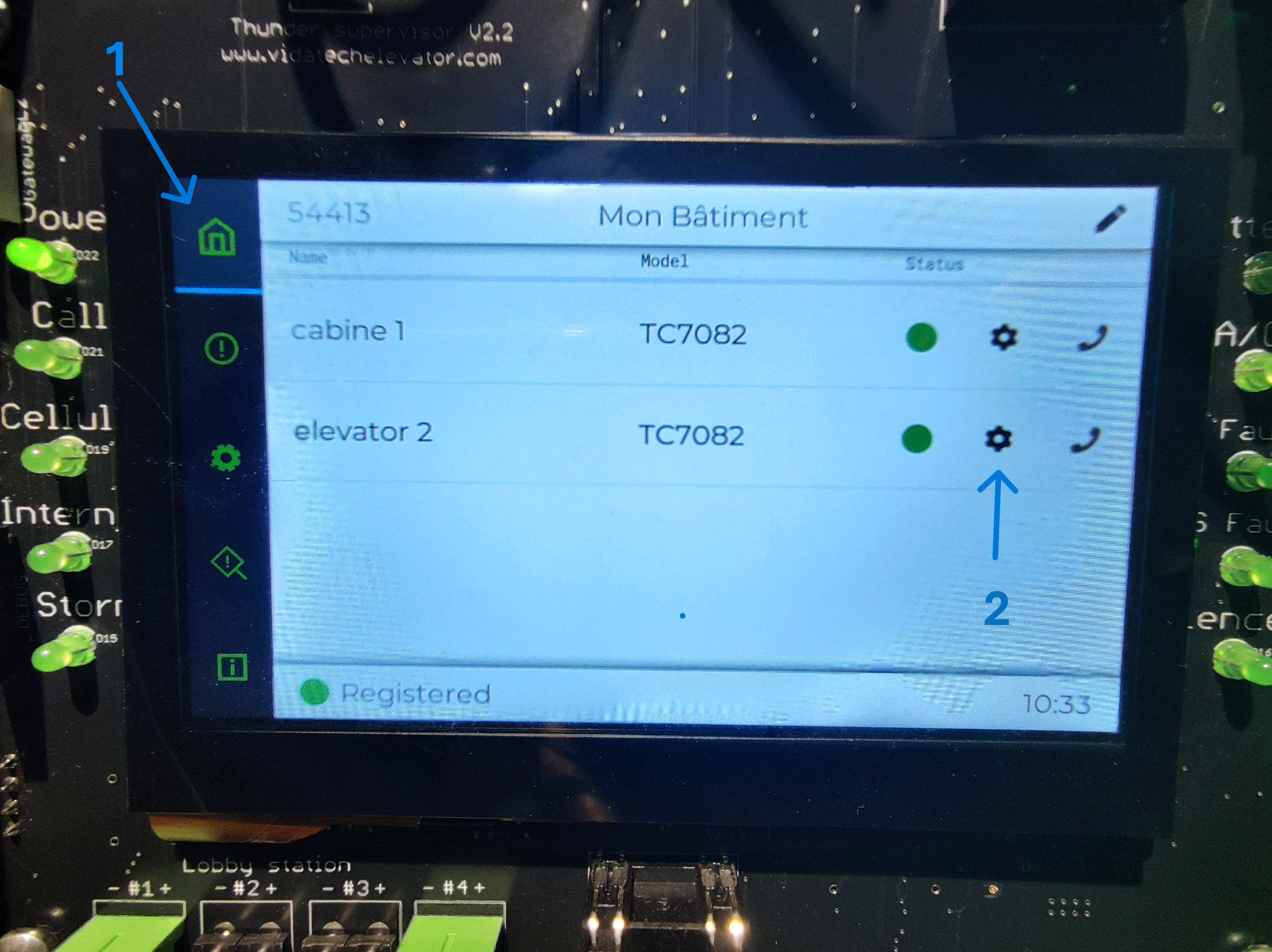
On the supervisor screen, follow the steps below:
-
Access the Home menu.
-
Select the gear icon for the Thunder Phone you wish to pair with a TA0000.
-
In the LMA Number parameter, select the appropriate LMA number. This value must correspond to the LMA port on the gateway
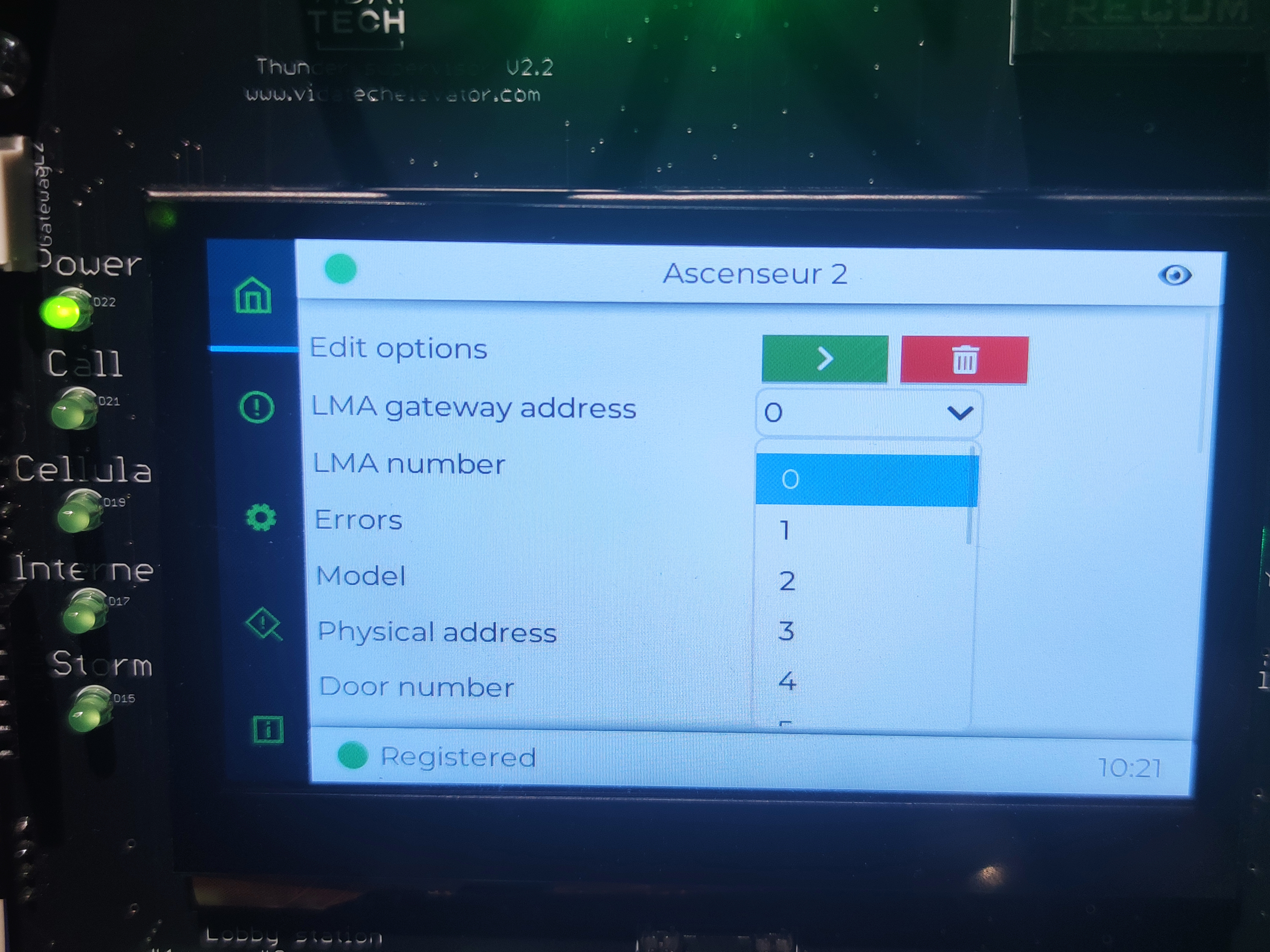
The LMA number parameter must match the LMA port on the gateway.
-
Configure the LMA gateway address. This address corresponds to the TG1232 or TG1264 located in the machine room. For a low-rise system, leave this parameter set to 0. For a high-rise system, the LMA gateway address must match the physical address of the TG1232 or TG1264.
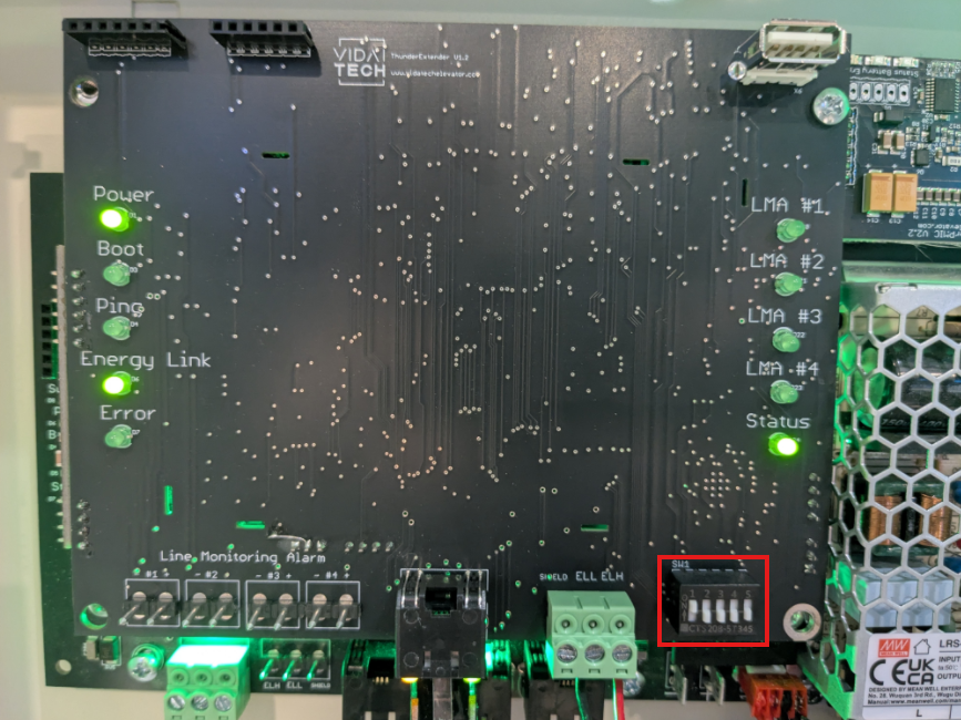
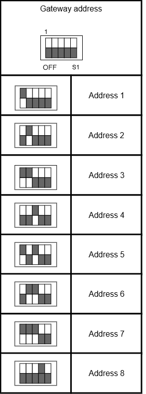
Each TG1232 or TG1264 must be assigned a unique physical address, starting at 1.
Configuration for the LULA system
The LULA system does not require any configuration. The Thunder Phone is automatically associated with the LMA.
Test and validation
To test the LMA, disconnect the internet connection. When the connection is lost, the LMA will enter an alarm state.